Build your own head tracker
My son has been playing a lot of the DCS World flight simulator lately, and started talking about building a head tracker. I didn’t even know this was a thing, outside of expensive Virtual Reality gear. A head tracker is a relatively low cost device that allows you to control your view in a game (look around the cockpit) just by moving your head - so you can keep your hands focused on steering and throttle, etc. He had read about building an infrared based tracker for $10 - but the parts needed didn’t seem convenient (PlayStation 3 camera and a floppy disk? - google it, you may like that solution better). Since I have experience with programming a Teensy, I knew it was possible to create a relatively cheap device that could simulate a game controller. After searching for “head tracker teensy” I came across this Inertial Head Tracker post which had the exact same idea, and had already done most of the hard work for me.
However, some of the details on that post were a little unclear, and I had a lot
of trouble with the source code on that page - I have a feeling it was corrupted
somehow in the publishing process because some of it just doesn’t make sense and
will not compile. I’m going to add my interpretation, and code, for what needs to be
done, but defer all credit for this idea to cmarzano, the author of that post.
Parts
- Teensy 3.2 w/pins - you might be able to save some money by using the Teensy-LC - I have not tried it. Newer versions of the Teensy should also work. I bought the version with pins to save me some soldering work.
- Teensy Prop Shield w/Motion Sensors - it should be obvious that you cannot use the low cost Prop Shield, since the motion sensors are the part we need.
- A long micro-USB cable. Long enough to allow freedom to connect the device on your head to your computer. I went with one of these 10ft cables.
-
Some header pins to make it easier to mount the Prop Shield on the Teensy.
- Teensyduino IDE - used to compile and publish programs to your Teensy.
Instructions
These instructions were mostly lifted from the original post - the original author deserves the credit, I just added some clarification on parts that confused me.
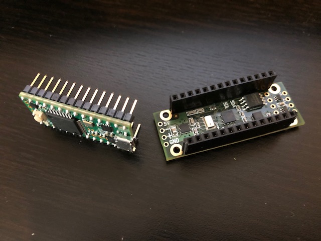
1) You need to connect the Prop Shield to the Teensy. The easiest way (assuming you have a soldering iron, and know how to use it), is to attach some female header connectors to the Prop Shield. You only need to connect the long sides. Connect the male header connectors to the bottom of the Teensy (or buy the version with pins). If you do not want to use header connectors, look at the diagram and table in the “Technical Details” section of the Prop Shield page to identify the pins that need to be connected to make the sensors work (follow the Used By column in the table). The header connectors make it easier to remove the Teensy from the Prop sheild, but if you want a permanant connection, you can probable get a lower profile by not using headers.
2) Mount the Teensy+Prop to a hat or headset. I 3D printed a small box to hold it, and used some heavy duty velcro to attach it (stick the soft side on the headset). It is important to mount it before calibrating it, since the calibration is impacted by other things around it.
3) Install and configure the Teensyduino/Arduino software. Open Teensy/Arduino -
the first thing you should do is go to the Tools menu and choose your Board (Teensy 3.2 for me).
Now when you open the File | Examples menu, there should be a Teensy 3.2 section that includes NXPMotionSense.
If you don’t see the NXPMotionSense examples, you can download them from the NXPMotionSense github page, click on Code, and Download Zip. Extract the zip to a directory.
Open the CalibrateSensors example sketch from the NXPMotionSense group. (File | Examples | NXPMotionSense | CalibrateSensors).
Or File | Open and find the sketch in the examples directory of the extracted zip.
4) Click the Verify button (or Sketch | Verify menu)
to make sure it works. If it compiles, connect the Teensy to your computer with
the USB cable, and click the Upload button. This should start running the CalibrateSensors
program on the Teensy. You can open the Serial Monitor from the Tools menu to
see the calibration data output. You should notice different numbers change, depending
on how you position the Teensy. After confirming it is working, close the Serial Monitor
so that it does not interfere with MotionCal in the next step.
5) Download and run the MotionCal application from the Prop Shield page. Select the COM port for the Teensy. Move the Teensy around through all axis of rotation - you should see the red dots start to form a sphere. You need to move it around until all of the numbers are below 5%. Once you reach that goal, the “Send Cal” button will be enabled. Press that button to write the calibration data to the Teensy’s EEPROM.
6) Open the MahonyIMU example sketch from the NXPMotionSense group (File|Examples|NXPMotionSense|MahonyIMU)
In the Teensy IDE, change the USB Type from Serial to “Flight Sim Controls + Joystick”.
Click the Verify button. If it works - great! But you will likely get a fatal error stating that it cannot find MahonyAHRS.h.
You need to install the MahonyAHRS library. As of this writing, the version (1.1) available in the Arduine Library Manager
does not work. You need to install the latest unreleased copy from the source. Go to https://github.com/PaulStoffregen/MahonyAHRS,
click Code, Download Zip. Extract the zip to your Arduino libraries directory (which is likely Arduino/libraries in your user Documents directory).
With the library installed, you should be able to Verify the sketch successfully. (I did see some warnings but they can be ignored).
Once it is successfully verified, upload it to the Teensy.
7) from the original post
Put your headset on and open the Arduino Serial Monitor. You will see the current values of heading, pitch, and roll in order. The values shown will vary with each setup depending on the mounting orientation of your Teensy and the direction your computer desk is facing. Note the heading value when you are looking straight ahead after about 1 minute has elapsed. The 1 minute wait is necessary for the algorithm to reduce the error with the magnetometer.
8) Create a new Sketch (File | New), paste in the code from below, and save it as HeadtrackJoystick.
Change the headingcenter=328 in the void setup() function and set it to the
heading value you observed when facing your computer (from the previous step). This determines
the center position of the joystick.
9) from the original post
Save the updated code to a safe place and flash the Teensy. It is now functioning as a USB joystick. You can view the output in the Arduino Serial Monitor for debugging if necessary, or launch the Windows “Set up USB Game Controllers” application to see windows receiving the data.
10) from the original post
Launch OpenTrack and adjust the input to use the Teensy. Depending on your luck, you may need to invert axes to match your movement. You can also adjust sensitivity, smoothing, and define curves in OpenTrack. For the output settings, set the interface option as “Use TrackIR, hide FreeTrack” to be compatible with most TrackIR compatible applications. I highly recommend setting a bind key for “Center” under “Options” to have the software adjust the resting center. This is to account for small differences in your positioning as every time you use the head tracker, you will have a slightly different resting position.
Code
Instead of using the code from the original post, use mine below (or, if gets mangled like it did on the original post, you can always get the latest version from my Github).
// HeadtrackJoystick, based on:
//
// Inertial Monitoring Unit (IMU) using Mahony filter.
// https://github.com/PaulStoffregen/NXPMotionSense/blob/master/examples/MahonyIMU/MahonyIMU.ino
//
// and inspired by the code example on http://crispycircuits.blogspot.com/2018/06/inertial-head-tracker.html

#include <NXPMotionSense.h>
#include <MahonyAHRS.h>
#include <Wire.h>
#include <EEPROM.h>

NXPMotionSense imu;
Mahony filter;

int joyheading;
int joypitch;
int joyroll;
float headingcenter = 180;
float headingoffset;
float adjustedheading;

void setup() {
  Serial.begin(9600);
  imu.begin();
  filter.begin(100); // 100 measurements per second

  //TODO: make this settable by pressing a button
  headingcenter=328;
  headingoffset = headingcenter - 180;
}

void loop() {
  float ax, ay, az;
  float gx, gy, gz;
  float mx, my, mz;
  float roll, pitch, heading;

  if (imu.available()) {
    // Read the motion sensors
    imu.readMotionSensor(ax, ay, az, gx, gy, gz, mx, my, mz);

    // Update the Mahony filter
    filter.update(gx, gy, gz, ax, ay, az, mx, my, mz);

    // print the heading, pitch and roll
    heading = filter.getYaw(); //  0..360
    pitch = filter.getPitch(); //  -90..90
    roll = filter.getRoll();   // -180..180

    Serial.print("Orientation: ");
    Serial.print(heading);
    Serial.print(" ");
    Serial.print(pitch);
    Serial.print(" ");
    Serial.println(roll);

    // The heading is a number retrieved from the sensor, which indicates a
    // compass direction (degrees) using a number from 0-359.
    // We want to use that number from a sensor to indicate which way our
    // "joystick" is pointing. If you are looking straight at your computer,
    // the joystick should be centered, and you can look up to 180 degrees in
    // each direction.
    // Since not everyone will be looking due South at the their computer, we
    // need to map their actual heading (specified by headingcenter) so that it
    // can be used as the neutral position of the joystick. The adjustedheading
    // is the actual heading, mapped to a new 360 degree range.
    adjustedheading = heading - headingoffset;
    if (adjustedheading < 0){
      adjustedheading = adjustedheading + 360;
    }
    if (adjustedheading > 360){
      adjustedheading = adjustedheading - 360;
    }
    // The heading value from the sensor has 360 values. The Teensy joystick
    // driver expects a value from 0-1023, with 512 indicating the center. Map
    // the sensor value as a fraction of the joystick range.
    joyheading = (adjustedheading / 360) * 1023;
    // The pitch value from the sensor has 180 values. Map the sensor value as
    // a fraction of the joystick range.
    joypitch = ((pitch + 90) / 180) * 1023;
    // The roll value from the center has 360 values. Map the sensor value as
    // a fraction of the joystick range.
    joyroll = ((roll + 180) / 360) * 1023;

    // Send the sensor data as joystick input to the computer
    Joystick.X(joyheading);
    Joystick.Y(joypitch);
    Joystick.Z(joyroll);

    Serial.print("Joyvalue: ");
    Serial.print(joyheading);
    Serial.print(" ");
    Serial.print(joypitch);
    Serial.print(" ");
    Serial.println(joyroll);
  }
}