Infinity ErgoDox Build Guide Companion
This article is intended to be a companion to the official Infinity ErgoDox build guide maintained by Input Club. As a first-time keyboard builder, there were a number of steps that were not very clear to me. My hope is that this will help other novice builders build their keyboard with more confidence. It is not intended to replace the build guide, and it skips some steps that do not require any further clarification.
NOTE: You should be aware that there are two different build guides for the Infinity ErgoDox on the input.club site. Which one you get depends on the navigation steps you take. The one that appears to be the most up-to-date is the one I linked to above - you reach it by choosing “Infinity ErgoDox Kit” from the “Devices” menu on the input.club website, and then following the link to the Build Guide (it will have “devices” in the url). However, if you choose “FAQs” from the “Forums” top menu, and follow the “Build Guide: Infinity ErgoDox” link, you will see an older version of the build guide (it will have “knowledgebase” in the url).
Pre-step 1 warning:
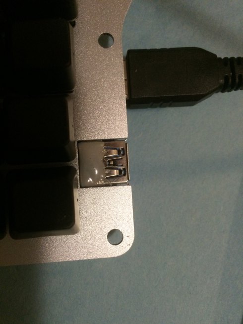
The latest version of the build guide (as of this writing) contains a warning before the first step about a potential weakness of the USB connectors. It suggests adding some solder to the pins, but those connections looked way too small for my soldering experience level and/or tools. Instead, I opted to reinforce all of the connectors with non-conductive metal epoxy, as suggested in the forums. The forums weren’t very specific on how much, so I covered the ports as much as I could. I spent too much money and waited too long to have the keyboard break on me now. But a bit of warning - it was only after I assembled the full keyboard that I realized the case is transparent, so my sloppy globs of epoxy on the USB-A connector are visible. I can live with that, as long as it all stays together, but you may want to be more careful to stay to the sides and back of those connectors (the micro-B connectors are covered after assembly, so it is okay to cover them - just be aware if you make the covering too thick, it may interfere with attaching the PCB to the switch plate).
Step 1:
Verify your components. I didn’t really know what I was looking for at the time, but after I assembled my keyboard I had one key that didn’t work, which I traced to a faulty diode. It was crooked, and the casing was slightly peeled back. I contacted Massdrop support as they suggest, and they sent me a few spare diodes right away. This is just a reminder that they are there to help if needed.
Step 3:
This step tells you to verify that you have all of the case layers. It lists them out, but unfortunately, the names like “Top Plate #1” didn’t mean much to me. I could count the layers and verify there were two of each shape. But throughout the build I was worried that I would mess up the order of the layers. I’m not sure if you can put them together improperly, but just in case, I’ve taken some photos to help you identify them:
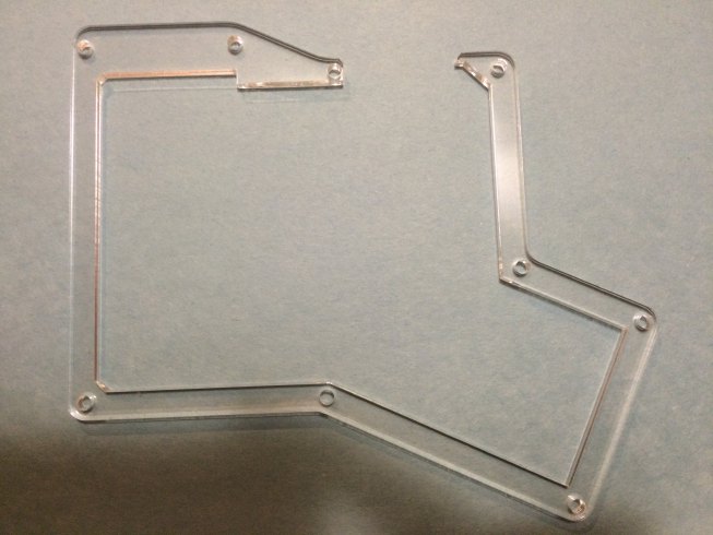
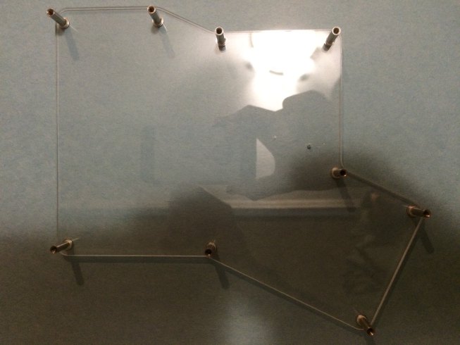
The top plates go above the switch plate. You can differentiate the top plates from the bottom spacer plates because the top plates are a closed shape that goes around the entire perimeter of the keyboard. The bottom spacer plates are open, in that there is a break in the perimeter (where the USB connectors go). Click the plate names to see a photo.
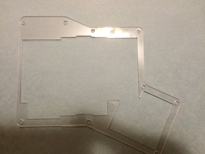
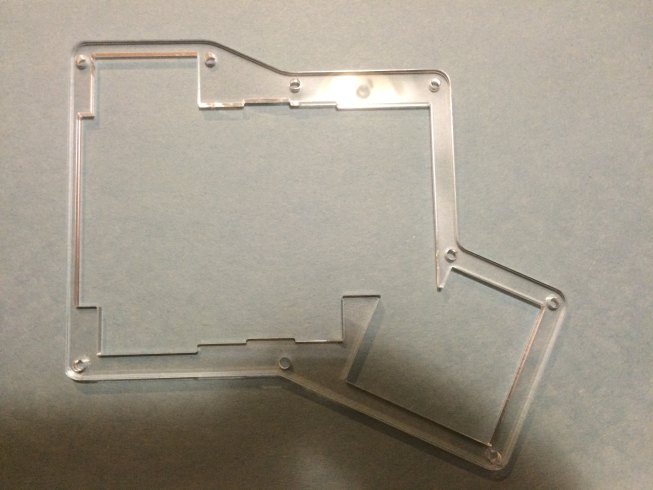
- Top Plate #2: the thinner of the two closed shapes. The acrylic covers the area where the LCD will be (top-left on left-hand keyboard).
- Top Plate #1: the thicker of the two closed shapes. There is an opening where the LCD will be.
- Switch Plate: this is more obvious, as the only aluminum piece.
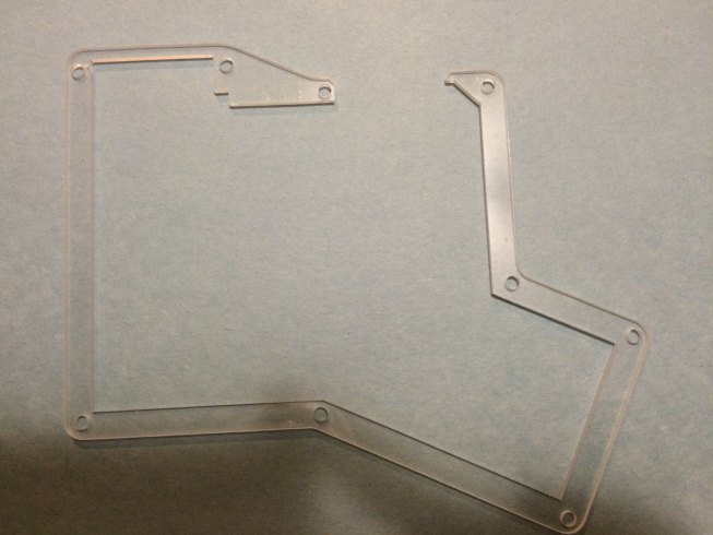
- Spacer Plate #1: the thinner of the two open shapes. It has a larger notch for the LCD.
- Spacer Plate #2: the thicker of the two open shapes. It has a small notch for the LCD.
- Bottom Plate: also obvious, as it is the only acrylic piece that doesn’t have a hole it the middle. It covers the entire bottom of the keyboard.
Step 4:
Remove the backing paper. I wish I had a good tip for this step. It took me much longer than I care to admit. You can probably do it a lot faster if you are more aggressive.
Steps 5-7:
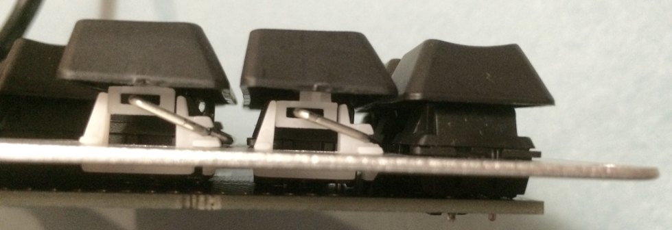
Definitely the most confusing steps in the guide. I think it assumes a lot more familiarity with stabilizers. They are the white plastic pieces that help keep the larger keycaps from wobbling on top of the switch. Hopefully a photo of the finished product will help you better visualize each step.
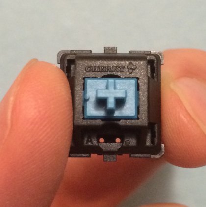
The other confusing part of this step is that it refers to the “stabilized switches”, and even shows a switch mounted on the switch plate, and yet none of the previous steps mentioned anything about mounting a switch! It wasn’t clear to me if I should be attaching a switch so early in the process. It turns out you can - but you’ll want to make sure you mount it in the correct direction. When the switch is face up (you can press in the mechanical button on the top), there are two clips on the north and south edges (I’m referring to a Cherry MX switch, I am not sure how much other brands differ). On the north side, you can see the word “Cherry” in the plastic. This is the same end that has the two pins on the bottom of the switch. When attaching the thumb keys that have the stabilizers, it is very important that you position the end of the switch with the pins so that they are closer to the inner/main body of the plate. The other end is toward the outer/thumb area edge of the plate.
Step 7:
This is the most vague step. At this point you should have two long white plastic stabilizer inserted into the switch plate (for each stabilized key), and a switch mounted in between them (pins closer to the main portion). Attach the wire to the two stabilizers as shown in the build guide, with the wire going along the edge closer to the outside of the keyboard. Now locate the keycaps that will attach to the stabilized switches. If you bought your keycaps from Massdrop, these will be the largest size keycaps. They have three holes on the bottom. The middle hole will attach to the switch. For the other holes, you need to insert the small white plastic pieces that came with the stabilizers. When “face up” (the part that will insert into keycap on top), there is a longer portion that extends from one end. You want this end facing toward the inner body of the keyboard. Figure out which way you want to mount your keycaps (mine have one side that is vertical, and the other side is slanted - I chose to mount mine with the vertical side facing the inner part of the keyboard), and then attach the two white inserts in the outer holes on the keycap so that the long edge of the inserts face the correct direction. Now press on the middle of the wire so that the ends angle up slightly. Connect the keycap with the inserts to one edge of the wire, by pushing the wire through the hole on the insert. Then try and angle the keycap down so that you can put the other end of the wire into the hole on the other insert. This can be tricky. I used a tiny screwdriver to push out against the side of the wire to make it open wider when attaching the second insert. Once the wire is in both ends, try and position the “button” on the switch so that it is lined up with the middle hole on the keycap, and then push down firmly. Press the key a few times to make sure it is connected, and slides up and down easily. The stabilizer might “catch”, preventing the key from rising back to its proper height. This seems to be a common problem. I fixed mine by just pressing it a bunch and it worked itself out. Other people suggest lubricating the stabilizers. This video shows is a good demonstration of attaching the keycap to the stabilizers and switch, and also shows how to lubricate them, if needed.
Step 8:
Again, take care that you orient the switches correctly. It helps to look at the PCB to see the holes through which the switch pins will go. The switches will attach to the side of the PCB with the LCD face up. In most places, this means the pins of the switch will be on the south edge (so the Cherry logo is upside-down). There are a few places where the switch is oriented side-ways - in those cases, the pins should be oriented so that they are on the edge closer to the inner part of the keyboard.
Step 9:
If you have trouble attaching the switch plate to the PCB, you probably have some of the switches in the wrong direction, so the pins aren’t lined up with any holes (I had this problem my first time). Remove the misplaced switch (squeeze the 2 clips on the top and bottom) and re-position.
Step 10:
After soldering on the stabilized switches, I think its a good idea to verify things are working properly. Plug the PCB back into computer (as in Step #2) and press the keys. Hopefully, you should see the proper response from the computer. See the configurator to get an idea of expected functions of each key in the default layout. The stabilized keys should be (left hand) Backspace and Delete, and (right hand) Space and Return. I did this verification occassionally throughout the entire process of soldering on the rest of the switches (unplugging from the computer during the soldering steps).
Step 13:
This is a good point to flash your keyboard with the latest firmware. The layout that comes pre-installed does not include a function for entering Flash mode, which means you need to disassemble the keyboard (so that you can press the flash button on the bottom of the PCB) any time you want to upgrade the firmware/change the layout. The latest firmware maps a key to Flash mode, so you do not have to press the button on the bottom.
Step 16:
Installing the (optional) LEDs is mostly straightforward, but there are a couple tips that will make things go more smoothly. After you have pushed the LED through the switch and PCB (correctly oriented so the long wire goes through the square hole), make sure it is in as far as it will go before you solder it. I held a finger against the LED on the other side of the board while I soldered it to make sure it didn’t slip out at all. If the LED sits just a small amount above the switch, it may interfere with the keycap when you press the key. After the two wires are soldered in, you’ll need to trim them as close to the solder joint as possible. If the wires extend too long, they will make it difficult to attach the backplate and get a tight seal, and put extra pressure on the solder joints. However, be careful when clipping the wires - make sure you dont clip any adjacent components on the board.
Step 18a:
I already mentioned that Step 13 is a better time to flash your keyboard - not sure why they suggest waiting until you have it stacked on all of the acrylic pieces. However, this is a good time to consider drilling a hole in the backplate to allow access to the flash button on the PCB. Since the backplate is attached to the PCB (but not screwed it), you can mark the location for the drill hole above the flash button with a small marker. Then you’ll remove the backplate and do the drilling.
WARNING: Massdrop does not recommend the drilling step, as you may seriously crack or damage the acrylic. It worked well for me and others, but there is definitely risk involved.
Step 20:
Installing DCS caps is a bit tedious. The first step is to sort all
of the keycaps into the four different slopes (1-4). This can be a little
tricky, as they can look very similar. If you look at an individual keycap from
above, you’ll notice that one of the four sides is not sloped. Organize all of
your keys so that the side without the slope is on the left. If you line up keys
against each other, with the unsloped end aways on the left, you will be able to
tell if they are the same or not. If they are the same, place the match in line
behind the first one. If the are not the same, place it to the side to start a new line.
You should end up with four different lines. This photo should help you identify
the keyboard row number for each line (in increasing order from left to right):
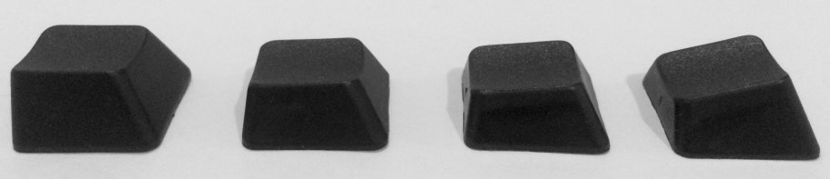 Row 1 is the tallest and row 4 has the steepest top slope.
Once you know the row number, you can use this illustration as a guide to where each type of keycap belongs.
When you attach the keycaps, the non-sloped side should face either the top (north)
end of the keyboard, or the inner part of the keyboard (if it is a sideways key).
Row 1 is the tallest and row 4 has the steepest top slope.
Once you know the row number, you can use this illustration as a guide to where each type of keycap belongs.
When you attach the keycaps, the non-sloped side should face either the top (north)
end of the keyboard, or the inner part of the keyboard (if it is a sideways key).
Conclusion
I plan to post a follow-up article with instructions on customizing your keyboard layout. Until then, check out the online configurator and the controller code wiki.
You should also check out the burritoware commentary, as I found it helpful during my first build.
If any of the steps above need correction or clarification, please mention it on the input.club forums, or contact me on twitter.

Infinity Ergodox Build Guide Companion by Joshua Flanagan is licensed under a Creative Commons Attribution-ShareAlike 4.0 International License.
Explicit permission is granted to the Infinity ErgoDox Build Guide hosted at http://input.club/devices/infinity-ergodox/infinity-ergodox-build-guide to incorporate any portion of this work without attribution.